P2
Practical 2 Air Lift Pump Challenge
Member | Roles | Responsibilities |
Steward | Team leader | Ensure all the procedures are executed |
Yu Nander Aung | Experimenter | Set up and carry out the hands-on part of the experiment |
Kit | Timekeeper | Record the time, tabulate data and plot graphs |
Steward, Nander, Kit | Blogger | Consolidate and type the documentation in the blog |
- Air pump device
- U-shaped tube
- Polyvinyl chloride (PVC) tube
- Containers
- Weighing Scale
- Stapler
- Marker
- Scissor
- Scotch tape
- Ruler


Illustrations | Steps |
 | Cutting out a strip of plastic from a food container. |
 | Roll it into a cylinder with a diameter of about 25mm. |
 | Use staple to secure the cylinder. |
 | Finished product. |
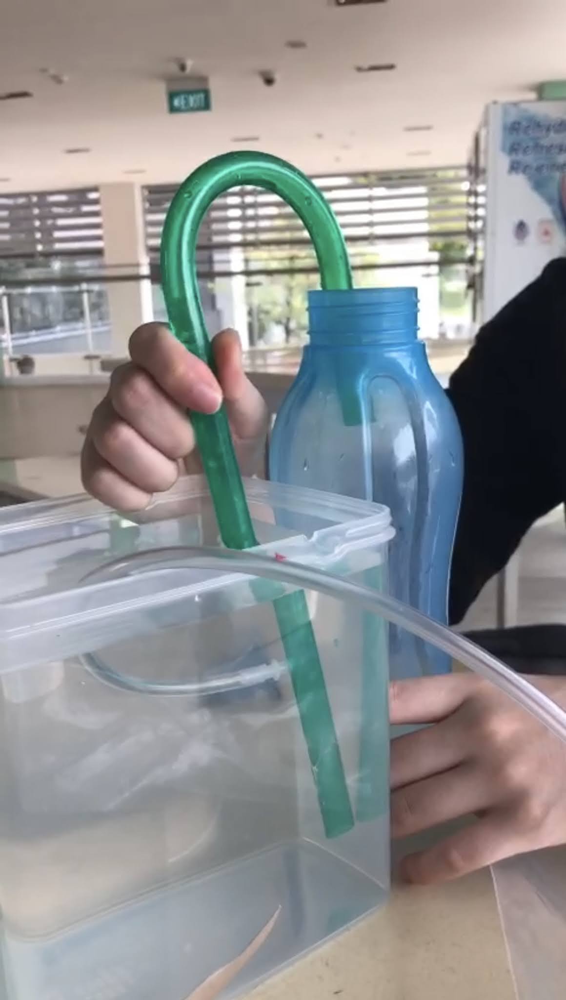
2.3 Putting Everything Together
- One end of the PVC tube was connected to the air pump device.
- The other end is connected to the U-shaped tube.
- The cylinder was put on the U-shaped tube to ensure that the PVC tube is held in place.
- Place the U-shaped tube into bucket of water.
- Next put the empty container onto the weighing scale and tare the weighing scale.
- Tape the U-shaped tube onto the container filled with water to ensure the tube is secure.
- Plug in the air pump device and switch on the air pump device.


Fix the U-shaper tube to be 10 cm from the base of the container holding wate (b=10cm). Measure the volume of water collected. Adjust the length of the tubing inside the U-shape tube such that a=2 cm. Slide the hose segment up or down so that PVC tube does not dislodge from the U-shape tube and does not have any kink. Turn on the air pump and determine the pump flowrate. Repeat the test 3 times and average the timing. Repeat the experiment with different values of a from 2 to 10cm.
b = 10cm
Table 3: Data Collection for Experiment 1
a (cm) | X (cm) | Flowrate (ml/s) | Average Flowrate (ml/s) | ||
Run 1 | Run 2 | Run 3 | |||
2 | 12 | 7.08 | 7.28 | 7.08 | 7.15 |
4 | 10 | 4.25 | 4.63 | 4.25 | 4.38 |
6 | 8 | 3.03 | 3.23 | 3.37 | 3.21 |
8 | 6 | 1.07 | 0.9 | 1.3 | 1.09 |
10 | 4 | 0.28 | 0.33 | 0.48 | 0.37 |
Flowrate is volume of water collected/transferred divided by time taken
Experiment 2
With a fixed at 2 cm, adjust b to 12 cm. Measure the pump flowrate. Repeat the experiment with different values of b from 12 to 20 cm.
a = 2cm
Table 4: Data Collection for Experiment 2
b (cm) | Y (cm) | Flowrate (ml/s) | Average Flowrate (ml/s) | ||
Run 1 | Run 2 | Run 3 | |||
10* | 14 | 7.08 | 7.28 | 7.08 | 7.15 |
12 | 12 | 2.73 | 3.20 | 3.08 | 3.00 |
14 | 10 | 0.83 | 1.48 | 1.47 | 1.26 |
16 | 8 | 0.22 | 0.23 | 0.13 | 0.19 |
18 | 6 | 0.00 | 0.00 | 0.00 | 0.00 |
20 | 4 | 0.00 | 0.00 | 0.00 | 0.00 |
Flowrate is volume of water collected/transferred divided by time taken
Note: * is taken from experiment 1 as it has to same parameters
Section C Questions & Tasks
1. Plot tube length X versus pump flowrate. (X is the distance from the surface of the water to the tip of the air outlet tube). Draw at least one conclusion from the graph.

2. Plot tube length Y versus pump flowrate. (Y is the distance from the surface of the water to the tip of the U-shape tube that is submerged in water). Draw at least one conclusion from the graph.

3. Summarise the learning, observations and reflection in about 150 to 200 words.
Experiment 1:
Some of the things that were observed were the flowrate of water decreases as ‘a’ increases or ‘X’ decreases. ‘a’ has a relationship with ‘X’, where when ‘a’ increase, ‘X’ will decrease. It is observed that the flowrate of water decreases when the length between the water surface and the tip of the air outlet decreases, this is due to lesser water pressure when the tip of the air outlet is at a higher point, hence lesser water is being pushed out.
Experiment 2 :
Similarly, as the ‘Y’ value decreases, the waterflow rate decreases. And as ‘Y’ decreases ‘b’ increases. Since when ‘Y’ value decreases, the distance from the water surface to the bottom of the curve tube decreases, hence there is lesser water pressure hence lesser amount of water is being pushed out of the tube together with the air being pumped by the generator. The flowrate decreases until there isn't enough pressure to pushed out the water hence flowrate reaches 0 eventually. During which, the noises of water bubbles get louder.
4. Explain how you measure the volume of water accurately for the determination of the flowrate?
The volume of water is measured using a weighing scale. The density of water at room temperature and pressure is 1g/ml, so we used this density to convert mass to volume. The bucket that was used to collect water is always on the weighing scale.
Before each run, the weight of the bucket is tarred so that the mass of water is measured accurately. During the run, the time taken is 30s. After obtaining the mass of water, it is divided by density of water which is 1g/ml to obtain the volume. The flowrate is obtained by taking volume divided by time taken (which in our case is 30s).
This method is more accurate than using a measuring cup or cylinder to measure the volume. This is because towards the end of each experiment, the volume of the water collected decreases gradually. It will be more difficult to measure the volume using measuring cup or cylinder as there may be parallax error. Therefore, measuring the volume of water collected by weighing the mass of water collected is an accurate way to determine the water flowrate.
5. How is the liquid flowrate of an air-lift pump related to the air flowrate? Explain your reasoning.
The liquid flowrate of an air lift pump is related to the air flow rate. The higher the air flowrate, the higher the liquid flowrate of an air-lift pump. This is because when the generator is working, air is being pumped from the generator into the plastic tubing which is connected to the curve tube. When the air is pumped, the air bubble fills up the small cross section of the plastic tubing, where the air displaced the water. This is due to air density being much lower than that of water, hence it floats up, occupying the cross section of the plastic tube, pushing the water up at the same time. Thus, air flowrate is directly proportional to liquid flowrate, as the air flowrate increases, the liquid flowrate increases.
6. Do you think pump cavitation can happen in an air-lift pump? Explain.
Pump cavitation is the vaporisation of liquid which occurs if the pressure of the liquid at the air-lift pump suction is less than vapour pressure. Bubbles of vapour will form and move towards a region of high pressure inside the pump where they will collapse. Cavitation is called the formation and collapse of vapour bubbles in the air lift pump. As such, pump cavitation can happen in an air-lift pump because if the air pressure is below the vapour pressure PV of water, cavitation will occur. Since PV is the minimum pressure that can be obtained at the entrance of pump, the suction flow at this point is the maximum that can be obtained with the particular value of the suction head. Attempts to reduce air pressure below PV will simply lead to greater vapour volumes at PV in the suction fluid. This induces cavitation in a pump as a result of decreased air pressure.
7. What is the flow regime that is most suitable for lifting water in an air-lift pump? Explain.
The flow regime that is the most suitable is laminar flow. This can be calculated using the concept of Reynold’s number. It is measured that the diameter of the tube is 1.2cm, so D = 0.012m. The density of water is approximately 1000Kg/m3, so ρ = 1000Kg/m3. The viscosity of water is 0.001Kg/m.s. Both density and viscosity of water is found online. Velocity can be calculated using flowrate divided by area, the chosen flowrate is 7.15ml/s because it is the highest.

Since Reynold's number is less than 2100, so the most suitable flow regime is laminar.
8. What is one assumption about the water level that has to be made? Explain.
It is assumed that the water level is constant at all times whenever it is poured back into the big container. This is because there are some remnants of the water in the smaller container whenever the water is poured back to the big tank. Not all the water is able to be poured out from the small container to the bigger one hence this may leads to some inaccuracy. It is to be assumed that the water collected after each run that were pour backed into the container is the original amount of water.

Excellent work done, team. The video taken appears to not show faces of the team members on a laptop. It is okay.
ReplyDelete